IgE-81
WELLPOINT
SYSTEM
Operating Instructions
Structure and Operation Specifications

Manufacturer:
P.P.H.U.
„KLAUDIA” sp. z o.o.
43-450
Ustroń, J.Kreta 24, woj. śląskie
tel. +48 33 854 74 36, tel./fax: +48 33 854 28 40
Internet: http://www.klaudia.eu
e-mail: klaudia@klaudia.eu
1. SPECIFICATIONS
1.1. Introduction
Wellpoint systems are broadly used and recognized in the construction of
drainage systems for building trenches/excavations. This is due to needs dictated by local
hydrogeological conditions and the usable value of these drainage inlets.
Wellpoint systems are designed for draining fine-grained soils, which do
not give water easily. Their
characteristic feature is a system of densely spaced inlets with small
cross-sections, connected in parallel via a suction header pipe with a pumping
engine.
Wellpoints are vacuum inlets/intakes.
Operation in negative pressure conditions requires that the wellpoint
system be maximally leaktight, and that pumping engines be able to generate
high negative pressure and to receive a considerable volume of air coming from
the soil through inlet filters.
The IgE-81 system is a subject solution for drainage, developed by
Polish scientists. Due to its
engineering and operational advantages, it has a leading position among other
solutions used by Polish contractors.
1.2. Designation and application
The IgE-81 wellpoint systems are designed to drain building trenches and excavations in low and
medium permeability soils (permeability coefficient k <40m/day).
The system may be used as an independent
installation or a support system for other drainage inlet types in
one- or two-level arrangements. One wellpoint level makes it possible to
lower the ground water table up to
The IgE-81 wellpoints are fitted to work without sand filling; sand
filling shall be used only in interbedded or dusty soils.
Depending on ground water inflow
conditions, trench size and the pumping
equipment at disposal, the quantity of wellpoints connected to the appropriate pumping engine
varies from 5 to 150
pieces. The most commonly used systems
are based on 50-100 wellpoints.
The main element limiting the quantity of wellpoints connected to a single pumping engine is the volume of air and
water that penetrates into the system through inlet filters, and which has to
be delivered by the pumping engine.
Pumping
engines characterised by a limited air uptake capacity may be used as
substitutes, reducing the quantity of wellpoints
connected to them.
1.3. Specifications of the lgE-81 wellpoint system
As compared to conventional structures, the
IgE-81 wellpoint system has the following properties:
§ reduced amount of work when
installing and uninstalling the system (connections between wellpoint and suction header pipe and between individual header
pipes are simple, quick and
leaktight),
§ easier transport
and reduced labour demand involved in transport (light materials for wellpoints and suction headers and reduced amount of
components),
§
high
wellpoint durability, which allows for their repeated use (wellpoint material
is resistant to corrosion and low temperatures, and the simple design of the
typical filter facilitates its cleaning),
§
two casing pipe types in two lengths, added to the
set, which make it easier to install wellpoints in different soil conditions and at any depth.
Wellpoint system options: IgE 81/32 and IgE
81/63
Wellpoint systems are available in two versions: IgE 81/32 and IgE
81/63. Both versions differ from each
other above all in the wellpoints that are used. The most commonly used version, IGE 81/32, is
based on flexible wellpoints,
In the case of the IGE 81/63 option, diameter 63 wellpoints are
used. This version allows for more efficient drainage. As
compared to version IGE 81/32, a flexible connector with gaskets is
additionally required for each wellpoint in order to connect it to the suction header
pipe. Also, the suction header and the stoppers that close its ferrules are different.
1.4. Description of structure and basic specifications
All metal elements of the system are made of
aluminium.
Pump flanged, coupling
joint - (item 1 on the list) has a flange on one end, and on the other a
tip with an inside fitting 133 (V-type – male end). The ferrule is an element used for quick
connection of the pumping engine to the wellpoint system suction header pipe
and discharge pipe. It should be
permanently screwed down (with a rubber gasket) to the pumping engine suction
ferrule and discharge ferrule.
Flanged distributor (item 2) has a flange on one end, as does the ferrule (item 1), and on the
other side it has two inlets ended with internal fittings 133.
The distributor is used (by screwing it down with a rubber gasket to the pumping engine suction ferrule) in those cases when drainage design provides for the usage of two
suction header (system) lines.
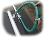
Flexible connector (item 3) is made of flexible reinforced PVC
hose (D 110mm), approximately 2.5m in length with a tip with an outside fitting
133 (M-type – female end) on one end, and on the other an inside fitting 133. The hose is sealed at the ends with rubber
inserts and fixed with metal bands.
The
connector is used to connect the wellpoint system suction header pipe to the pumping engine, or to alter the
direction that the suction header and
discharge pipe are lying.
Suction header pipe IgE
81/32 (item 4) is made of D 133mm tube,
The suction
header pipe is used to connect
wellpoints to the pumping engine, and it is a negative pressure collecting line
for all inlets/intakes.
Through pipe (item 5) is
made of D 133mm tube in two lengths (3 and
It is used
to extend the wellpoint system suction header
or to replace suction header pipe in these places, where no wellpoints
are installed.
Pipe bend 90° (item 6) is made of welded tube 133
sections, ending in fittings 133 (outside
and inside). It is used to change suction header or
discharge pipe direction by 90°.
Flexible wellpoint 32 (item 7) is made of flexible and
semi-transparent polyethylene tube 0
32x3.4mm, 7m in length, ending in a screened filter - length 0.3m, 0.6m or
1m. It is used to draw water
from soil.
Wellpoint gasket (item 8) is made of O-ring shaped rubber, size
0 23.5x7.7mm. It is used to ensure
leaktight connection between the wellpoint and the suction header ferrule.
Gasket 133 (item 9) is made of O-ring shaped rubber, size Æ 187x22mm. It is used to seal all suction header and
jetting pipe 133 (item 16) joints with jetting hoses (item 15).
Plug (item 10) is made of cut cone-shaped rubber,
size 038/046x40 mm. It is designed to close (stop) suction
header ferrules in the event that no
wellpoint is used in a given location, or if it
is put out of service due to emergency reasons.
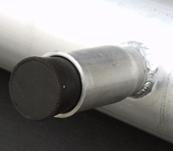
Outside stopper, end cap (item 11)
consists of a capped outside
fitting and a lever fastening. It is
used to close suction header end.
Moreover, it may be used to close off the pumping engine suction ferrule
(when it is provided with ferrule or distributor) while checking its ability to generate negative pressure.
Jetting
pipe 50 (item 13)
is made of D 50mm tube, ending on one side in an inside fitting, and used to install (set) wellpoints in soil without sand
filling.
Pipe length = 6 running metres.
Jetting hose 50 (item 12) bezalin-type D 50mm, length
Gasket 50 (item 14) is made of O-ring shaped rubber. It is used
to seal the joint between jetting pipe 50 and jetting hose 50.
Jetting pipe 133
(item 16) is made
of D 133mm tube, ending on one side
in an inside fitting and pull and on the other side in tooth-shaped cuts, and is used to install (set) wellpoints in soil when it is
required to use wellpoint sand filling.
It is offered in two lengths (4.5 and
Jetting
hose 75 (item 15) bezalin-type 0
75mm, length
NOTE: It is acceptable to make jetting
hoses using other pressure hose types (e.g. rubber, PVC, etc.).
Additional elements used in the Ige
81/63 system
Suction header pipe IgE 81/63 (item
17) is made of D 133mm tube, length
Suction
header is used to connect wellpoints to the pumping engine, and it is a
negative pressure collecting line for all inlets/intakes.
Flexible wellpoint 63 (item 18) is made of flexible and
semi-transparent polyethylene tube
63x5.8mm, 6m in length, ending on one side in a 0.6m-long screened filter and
on the other side in a M 51 tip. It is used to
draw water from soil.
Flexible connector
Gasket for flexible
connector
Jetting pipe 108 (item 21) - made of D 108mm tube,
ending on one side in an M-type fitting
and pull, and is used to install and jet water into wellpoints
in soil.
Optional elements
The
system’s optional elements are additional
discharge pipes (item 23 on the
list), which are discharge pipeline elements.
They may be used to:
§
remove
water discharged by the pumping engine,
§
extend
system sections; connect suction header pipes and system elements distant from
each other.
Discharge pipes
shall be selected for each set, depending on the operating conditions of the
system.
1.5. List of system elements
IgE-81
wellpoint system elements
|
|
Name of
the element |
Material |
Dimensions |
Elements
per 50 wellpoints system |
||||||||||||
|
1 |
Pump flanged coupling joint
|
Al. |
* specified dimensions for pumping engines AP- |
3 |
||||||||||||
|
2 |
Flanged distributor |
Al. |
* specified dimensions for pumping engines AP- |
1 |
||||||||||||
|
3 |
Flexible
connector
|
Al + PCV D 110 |
|
3 |
||||||||||||
|
4 |
Suction header pipe
|
Al. or PE |
|
10 |
||||||||||||
|
5 |
Through
pipe 133/5000
|
Al. |
|
option |
|
6 |
Pipe
bend 90°/133
|
Al. or PE |
|
2 |
||||||
|
7 |
Flexible wellpoint 32 |
PE + siatka stil. |
|
50 |
||||||
|
8 |
Wellpoint
gasket
|
Guma |
|
150 |
||||||
|
9 |
Gasket
133
|
Guma |
|
30 |
||||||
|
10 |
Plug
|
Guma |
|
20 |
||||||
|
11 |
Outside stopper |
Al. |
|
3 |


Equipment for jetting
|
12 |
Jetting
hose 51/7500
|
Al. + bezalin |
|
2 |
||||||||||||
|
13 |
Jetting pipe 51
|
Al |
|
1 |
||||||||||||
|
14 |
Gasket 51 for jetting hose
|
Rubber |
|
5 |
||||||||||||
|
15 |
Jetting hose 75/75000
|
Al + bezalin D 75 |
|
2 |
||||||||||||
|
16 |
Jetting pipe 133/6000
|
Al |
133/4500 type
133/6000 type
|
1 1 |

Note: Wellpoint system is delivered:
- in contractual sets (according to the list);
- as individual elements, according to specific
orders.
Elements used in the IgE-81/63 system
|
17 |
Suction header pipe
|
Al. |
|
10 |
||||||||||
|
18 |
Flexible
wellpoint 63
|
PE + siatka stilonowa +Al. |
|
50 |
||||||||||
|
19 |
Flexible
connector 51
|
Al + PCW |
|
50 |
||||||||||
|
20 |
Gasket
for flexible
connector
|
Rubber |
|
100 |
||||||||||
|
21 |
Jetting pipe 108/6000
|
Al. |
|
1 |
||||||||||
|
22 |
Outsider stopper 51
|
Al. |
|
20 |

Optional elements
|
23 |
Discharge
pipeline elements (Discharge pipe)
|
Al. |
133/3000 type
133/5000 type
|
Option Any amount |
The Diagram of IgE 81/32 Wellpoint System
|
1 - pump
flanged coupling joint 2 - flanged distributor 3 - flexible
connector 4 – suction header pipe IgE 81/32 5 – through
pipe 6 - pipe bend 90° |
7 – flexible
wellpoint 8 - wellpoint gasket 9 – gasket
133 10 - plug 11 - outside stopper 12 – pomp
unit |
1.6. List of elements in standard, contractual system sets
Contractual wellpoint system sets are
shown below. The system elements are
available to order in sets or as individual elements. When selecting elements, we may take into
account existing or expected system operating conditions. It is also possible to renovate system
elements such as wellpoints or suction header pipes.
The IGE 32/81 system contractual set
for 50 running metres of drainage
|
Item |
Element name |
Pieces/sets
50 running m. |
|
1. |
Suction header pipe - |
10 |
|
2. |
Outside stopper |
3 |
|
3. |
Flanged ferrule |
3 |
|
4. |
Wellpoint gasket Æ |
150 |
|
5. |
Rubber plug |
20 |
|
6. |
Flexible connector - |
3 |
|
7. |
Flexible wellpoint L7000 mm, filter |
50 |
|
8. |
Flanged distributor |
1 |
|
9. |
Jetting pipe |
1 |
|
10. |
Jetting pipe |
1 |
|
11. |
Jetting pipe |
1 |
|
12. |
Jetting hose |
2 |
|
13. |
Jetting hose |
2 |
|
14. |
Bend |
2 |
|
15. |
Gasket |
30 |
|
16. |
Gasket |
5 |
The IGE 32/81 system contractual set
for 100 running metres of drainage
|
Item |
Element name |
Pieces/sets
50 running m. |
|
1. |
Suction header pipe - |
20 |
|
2. |
Outside stopper |
3 |
|
3. |
Flanged ferrule |
3 |
|
4. |
Wellpoint gasket Æ |
300 |
|
5. |
Rubber plug |
40 |
|
6. |
Flexible connector - |
3 |
|
7. |
Flexible wellpoint L7000 mm, filter |
100 |
|
8. |
Flanged distributor |
1 |
|
9. |
Jetting pipe |
1 |
|
10. |
Jetting pipe |
1 |
|
11. |
Jetting pipe |
1 |
|
12. |
Jetting hose |
2 |
|
13. |
Jetting hose |
2 |
|
14. |
Bend |
2 |
|
15. |
Gasket |
50 |
|
16. |
Gasket |
10 |
The IGE 63/81 system contractual set
for 50 running metres of drainage
|
Item |
Element name |
Pieces/sets
50 running m. |
|
1 |
Suction
header pipe IgE 81/63 - |
10 |
|
2 |
Outside stopper |
3 |
|
3 |
Outside stopper |
20 |
|
4 |
Flanged ferrule |
3 |
|
5 |
Gasket for
flexible connector |
100 |
|
6 |
Gasket for
jetting hose |
1 |
|
7 |
Gasket |
30 |
|
8 |
Flexible connector - |
3 |
|
9 |
Flexible
connector – |
50 |
|
10 |
Flexible
wellpoint L6000 mm, Æ 63, filter |
50 |
|
11 |
Jetting
hose 75/108 L7500 mm |
2 |
|
12 |
Jetting pipe |
1 |
|
13 |
Bend |
2 |
|
14 |
Flanged
distributor |
1 |
1.7. Systems based on diameters 89, 108 and 133 mm
133mm is the main and most commonly used diameter for the IgE
system. The IgE wellpoint systems may be
also based on pipes and suction headers of 89mm and 108mm diameter. The table below shows the availability of
elements with specified diameters:
|
Item |
Element name |
Diameter: 89 aluminium |
Diameter: 108 aluminium |
Diameter: 133 aluminium |
|
1. |
Suction header pipe
- L‑5000 |
X |
X |
X |
|
2. |
Flexible connector - L-3000 |
-- |
X |
X |
|
3. |
Flexible connector for wellpoint |
-- |
-- |
X |
|
3. |
90°
bend |
X |
X |
X |
|
4. |
Flanged
ferrule |
X |
X |
X |
|
5. |
Flanged
distributor |
X |
X |
X |
|
6. |
Ferrule
133 / hose 110 |
-- |
-- |
X |
|
7. |
Ferrule V
133 / hose 110 |
-- |
-- |
X |
|
8. |
Outside
stopper |
X |
X |
X |
|
9. |
Gasket |
X |
X |
X |
|
10. |
Special
reducer 133/108 |
-- |
-- |
X |
X means that an element with
the specified diameter is available.
1.8. The IgE system variant with polyethylene elements
Another available variant of the IgE wellpoint system is one in which
certain elements (suction header pipes and bends) are made of modified HDPE
polyethylene.
The range of operation for a system like that is the same as in the case
of fully aluminium systems. It is
recommended that polyethylene elements be stored either under a roof or cover.
2. OPERATING INSTRUCTIONS
2.1. Installation of the lge-81 wellpoint system
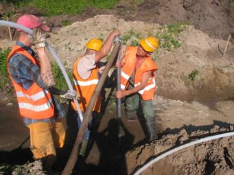
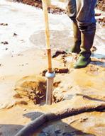
2.1.1. Wellpoint installation
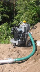
Wellpoints are installed (set) in soil using the
water jetting method with jetting pipes
connected to a water jetting pump or hydrant. The IgE81 wellpoint system set contains two
types of jetting pipes (casing pipes):
§
small diameter D
§
large diameter D
with
varying lengths in order to facilitate jetting into different depths.
Jetting pipe 51 (item 13) is used
to install wellpoints in soils which do not require filtration sand filling to
be used, and jetting pipe 133 (item 16) is
applied to jetting wellpoints in cases
when it is necessary to use sand filling.
Filtration
sand filling shall be carried out in:
§
interbedded
soils (containing impermeable layers) up to the height sufficient for sand
filling to interconnect all drained soil layers; most often, however, along the
whole height of wellpoint jetting;
§
homogeneous dusty soils, up to a height of about
Graining of
filtration sand filling shall be selected depending on the soil in which the
filter is to be set, according to the following rule:
D50/d50 = 5 ¸ 10
where: D50 = average sand filling
grain coarseness,
d50 = average soil
grain coarseness.
Wellpoints shall be installed every 1m along a predetermined line,
ensuring that all filters within the indicated wellpoint line (connected to a
single pump) are at one level.A team of 4-5 trained workers is required to
install wellpoints at the
construction site.
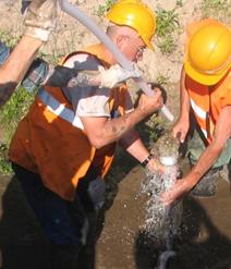
2.1.2. Procedure during wellpoint installation
The typical
sequence of operations when installing wellpoints is as follows:
§
connect jetting pipe (items 13 and 16 on the list) to water jetting
pump
or hydrant, using jetting hose (items 12 and
15),
§
if you are setting the wellpoint manually, position
the jetting pipe vertically with its edge on a support (e.g. piece of
thick board), next to the predetermined wellpoint setting location,
§
when you set the wellpoint with jetting pipe using a
crane, keep the pipe on the crane rope 150-
§
activate
water jetting pump or open the
hydrant,
§ when water
flows out of the jetting pipe, remove it from the support and lower it to the
ground.
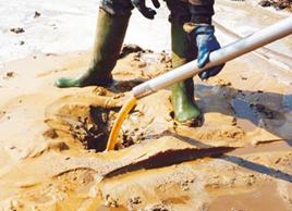
Note: Correct
lowering (penetration into the ground) of jetting
pipe is characterised by a steady
water outflow around the pipe. This is
achieved by properly manoeuvring the
jetting pipe (vertical and circular movements).
§
As soon as jetting pipe is driven down to the required
depth, water inflow should be stoped and the pipe
should be kept in this position for a moment, not allowing it to be
penetrated any deeper,
§
Disconnect jetting hose from jetting pipe.
Note: If
water flows out of jetting pipe after jetting hose has been disconnected, keep
lifting the pipe slowly until water stops flowing
out.
Further operations:
a) when setting the wellpoint with jetting
pipe 51:
§
insert
wellpoint into the pipe all the way down, proceeding with care so as not to
damage filter screen,
§
keep holding wellpoint (pushing it gently into the
pipe) and move the pipe vertically a few times (lift and lower it by
approximately 1m). When the lifted pipe
stops drawing out the wellpoint from soil, completely remove the casing
pipe.
b) when setting the wellpoint with jetting
pipe 133:
§
pour approximately ½ bucket of sand filling into the pipe,
§
insert
wellpoint into the pipe all the way down, proceeding with care so as not to
damage filter screen,
§
continue
carrying out sand filling down to the
designed depth,
§
keep holding wellpoint (pushing it gently into the
pipe) and withdraw the jetting
pipe from soil.
Note: 1) When withdrawing the jetting pipe,
proceed carefully so as not to pull out
the wellpoint from the sand filling.
2) Jetting pipe 133 shall be held by a crane
during water jetting and when it is pulled out (rope hooked over a special grip
on the pipe), or manually using loops made of hemp ropes or V-belts.
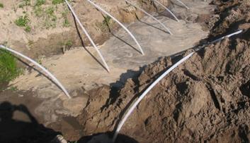
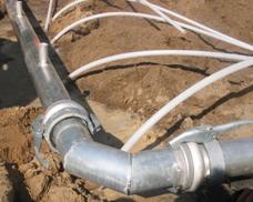
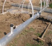
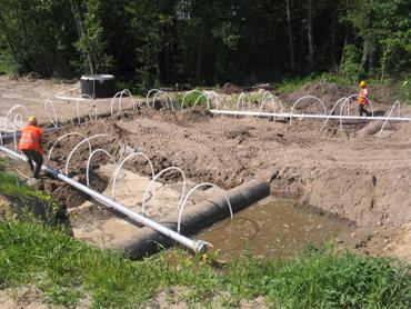
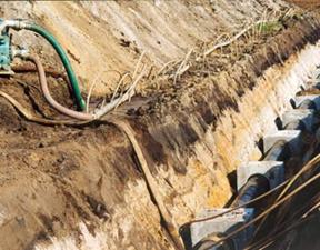
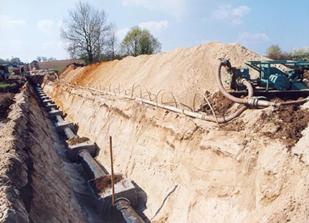
2.1.3. Suction header pipe installation and assembly
The wellpoint system suction header pipe shall be placed slightly
higher than the pump or
horizontally at an approximate distance of 0.5m from the line of already
driven-in wellpoints directly on levelled ground (ground surface,
trench/excavation bench) or on wooden supports placed near section joints. Suction header pipe sections
shall be laid with tips/ends with the outside fitting (lever
fastening) turned towards the pumping
engine. All header pipe ferrules used to make connections
with wellpoints must face up.
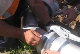
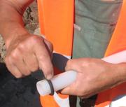
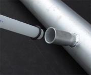
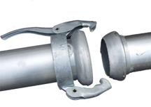
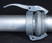
Assembly of the suction header pipe line (individual header
pipe sections, flexible connectors, bends, stoppers) involves putting ends together, placing the hook and
closing the lever.
Use flexible connector (item 3 on the list) or
bends (item 6 on the list) in order to change suction header pipe direction.
Use through pipes (item 5 on
the list) in order to extend suction
header pipe in places where wellpoints are not required. The header pipe end shall be closed with a
stopper/plug (item 11 on the list).
|
|
|

|
|
|
|


|
|
|

|
|
|
|
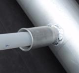
2.1.4. Connecting wellpoints to the suction header pipe
Wellpoints installed (set) in soil shall be connected to the suction header
pipe using O-ring-type rubber gaskets (item 8 on the list). This requires the above-mentioned gaskets to
be put onto wellpoint ends and moved
to a distance of 40-
Wellpoints shall be connected to the suction header pipe, ensuring that the height of all wellpoint bends
over the header pipe is as low as possible and identical. In the case of shallowly-set wellpoints, this may be achieved by moving the
header pipe in relation to already driven-in wellpoints.
When there are less wellpoints used than the
number of ferrules on the header pipe, free ferrules shall be closed with rubber plugs (item 10 on the list).
2.1.4. Connecting wellpoint system to the pumping engine
Flexible connectors (item
|
|
|
|
|
|
|

|
|
|
|
|
|
|
|

|
|
|


|
|
|


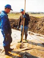
2.2. Operation of the system
It is recommended that the initial wellpoint system operation period
(from activation of the pumping engine until the intended depression has been
obtained) should be supervised by a specialist.
This operation period is used to verify the designed wellpoint system
working conditions (wellpoint setting/foundation depth, sand filling, number of
wellpoints connected to a single pumping engine, etc.), and to introduce
possible additions or modifications.
Further wellpoint system operation and work control shall be supervised
by trained employees. Semi-transparent
wellpoints and monitoring-measurement equipment (as vacuum meters, piezometers,
water meters) facilitate system work control.
The drainage system shall
include continuous water pumping. Water from the trench should be
removed to a distance higher than the depression sink range.
2.3. System disassembly/removal
The sequence of operations when removing the
wellpoint system after its work (draining) has been completed and the pumping engine has been switched off:
§ disconnect the
flexible connector from the pumping engine,
§ disconnect
wellpoints from the suction header pipe by removing them from ferrules,
§ remove rubber gaskets
from wellpoints, take out ferrule plugs and secure them,
§ remove suction
header pipe,
§ withdraw
wellpoints from soil,
§ remove (take
out) all rubber gaskets from joints.
After disassembly, all wellpoint system
elements shall be washed with water, cleaned, and protected
before further use.
2.4. Transport and storage
When transporting the system, a truck with min.
5m-long open load-carrying body is
required (due to the length of the elements). Suction header pipes and through
pipes shall be stacked in piles (layers shall be interleaved with boards), or
laid crosswise in layers (at a 90°angle).
All rubber elements (gaskets, plugs) shall be
kept in dark and cool places (preferably at a temperature of about
Wellpoint system elements do not require any
extra maintenance operations.
Note: Proceed with
special care during disassembly, cleaning, transport, and storage of the system
elements so as not to damage surfaces which contact rubber gaskets.
3. INDUSTRIAL SAFETY AND HYGIENE
When using wellpoint systems, follow the same industrial safety
regulations as those applicable for construction (earthworks, foundation works,
etc.) and transportation.
Workers employed for wellpoint system
installation and operation must be equipped with safety helmets, working
clothes, waterproof jackets, and rubber boots and gloves. Moreover, the following should also be done:
§
protect
trench slopes from possible sliding/creeping while driving-in wellpoints,
§
do
not install wellpoints under power lines,
§
check whether joints are leaktight and solid, and
eliminate possible bends of conduits delivering water to casing pipe,
§
secure
wellpoint system suction header pipe stability throughout operation period.
While operating the drainage system and
wellpoint jetting, the appropriate industrial safety regulations shall be
applied regarding the operation of pumps, electric motors, and combustion
engines, etc.
Be careful when handling the joint clamping
lever during system installation and removal and while jetting wellpoints.
CONTENTS